This circuit is not an origional idea of mine. It was taken from a "National Data Book". (1986 Linear Application Handbook.) However I designed the PCB for it.This circuit will give you a good, Accurate Watt Meter that can measure various power levels. In the Origional Article the Shunt was a .001 Ohm Copper Shunt giving a 1000 Watt Scale.
However, because Most Circuit Breakers in homes are 15 Amps, I made my unit to have a range of Zero to 1500 Watts.
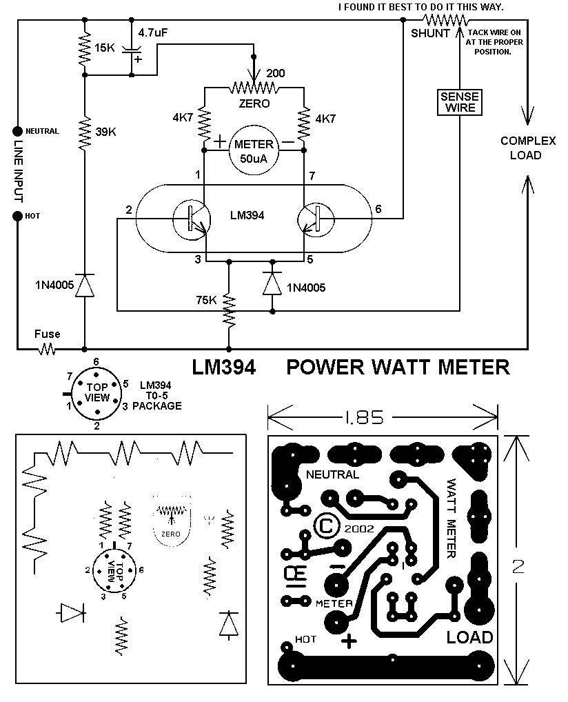
The Shunt on my unit is comprised of 5 small LOOPS in a Single piece of wire in an Inverted V Shape or an " _n_n_n_n_n_ " Shape, going from pad to pad. I used a #16 AWG wire, but you need to determine wire size and lengths based on the wattage range you choose.
This 16 AWG wire is a Bit Small, But it was what I had on hand. It probably should be a 14 AWG or even a 12 AWG for the 1500 watts. That would also be a Longer piece of wire. However, Extreme Accuracy wasn't an issue on my unit, so what I used is OK as it doesn't get overheated too much. Just a Bit of Drift in the reading as it "Slightly warms up".
A Smaller Shunt wire will cause "Heating and Resistance Changes". This will create errors and if Too Small can cause Extreme Overheating!" This Could be Very Dangerous and will Produce Poor Accuracy.
Additional Notes: 1) Load Current Sensing is only 10 mV, Keeping load voltage loss to 0.01%. 2) Rejection of Reactive Load Currents is Better than 100:1 for Linear Loads. 3) Non-Linearity is about 1% Full Scale when using a 50uA Meter. 4) Temperature Correction for Gain is accomplished by using a Copper Shunt (+0.32% / Degree Celsus) for Load Current Sensing. 5) This Circuit Measures power on the Negative Cycles only, Therefore it can Not be used on Rectifying Loads, Unless it is Isolated by a Transformer. 6) Idling Power Drain is 0.5 Watts.
Remember this Circuit works on "Live 110 AC Volts". Wire it Properly. An Inline Fuse would also be a GOOD Idea.
"HOME"
Complete Schematic, PCB and Layout, Larger View, "Click on it"
Click Here, Top View Picture of the Board.
Click Here, Enlarged Picture of My Shunt Notice how my Shunt is a Bit Longer than Needed. Also Notice how the Small Red wire is Tacked on to it at the Correct point.You will need to Determine Where to Attach this "Sense Wire" on your Wattmeter to get a Correct Calibration of it, using a Known Wattage.
All Imformation in this Article is "Copyright protected".

 Chemelec  *Copyright © 2002*