
Sorry, No PCB's for these Projects.
Presented here are Two Circuits
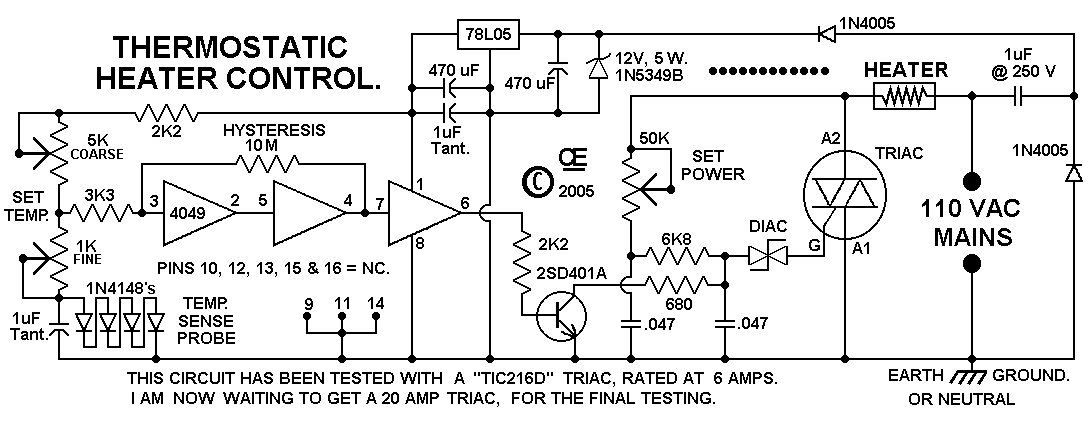
One Advantage of these two units is the Sensor can be placed Away from the heater, therefore sensing the Actual Room temperature, not the direct heat from the heater. These can also be used in a confined space with a Heat Lamp, to create a Drying Oven.This First Circuit was designed by me to replace the Mechanical Thermal Switches used in some Electric Heaters I have. The Electrical Contacts on these Mechanical Thermal Switches are getting pitted and are "No Longer Reliable". They could quite easily weld together, keeping this heater on Full. THAT IS DEFINATELY NOT GOOD! The Coarse Temperature Adjustment is a Trimpot on the Circuit Board, set to give a nominal range when using the Fine Adjust. The Fine Temperature Adjustment is a Standard Potentiometer with a Insulated Knob and/or Shaft to provide electrical protection against electric shock. Using this control you can set the harter to automatically turn "On and Off", Automatically Regulating the Room's Temperature. The Power Control for the Triac should be a 2 Watt Potentiometer, Also with a Insulated Knob and/or Shaft to provide electrical protection against electric shock. Or it can be a 2 watt resistor on the circuit board, set for an appropriate heat level. "Typically Full On", as that would be the Normal setting, when using the Mechanical Contacts. On the Schematic, I show a 10 Meg Hysteresis Resistor. This may be made Lower or Higher depending on how many degrees difference you want between On and Off cycles. Values between 100 K-Ohms and 22 Meg-Ohms are acceptable. The Disadvantage of a Triac is you will Not get 100% Efficiency.
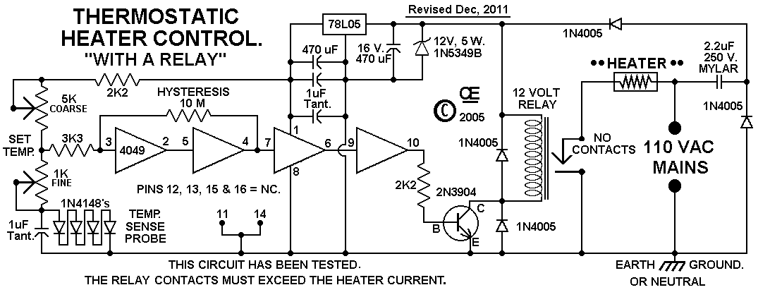
This Second Circuit is Simular in design, but uses a Conventional Relay. This will effectively give the 100% Efficiency. Even though the Schematic shows a 2N3904, I used a 2SD401A. Almost Any NPN Transistor is Acceptable. And other than a Power control, The Adjustments are the same as above.
 "The Schematic for the Triac Circuit."
"The Schematic for the Relay Circuit."
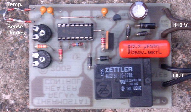
"A Picture of the Relay Circuit."
Chemelec *Copyright © 2005*
*Copyright © 2005*