USE EXTREME CAUTION, ELECTRIC SHOCK HAZZARD.
Build and Use it this circuit your own risk!
"Click Here to go Back to My Projects Page"
This is a Somewhat Experimental Circuit and I Especially designed this circuit for those persons that want to Dabble in Switching Power Supply Designs.
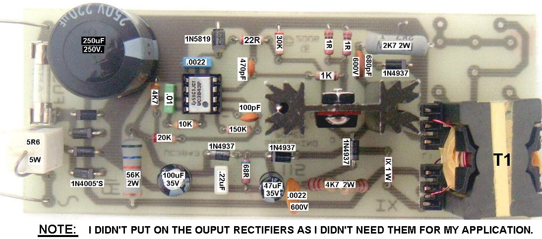
This Circuit is based on a UC3843 Integrated Circuit. It does Not allow for Feedback control of the output voltage. The output voltage is totally determined by the "Turns Ratio" in Transformer "T1". The Useable, Continuous Power Output is approximatey 25 watts or so. It could be used as a small Power Supply or a Battery Charger. In the proto I made, T1 has a Primary Inductance of about 1 mH. This requires 33 turns of 26 or 28 AWG Wire wound on the Bobbin First. (About One Layer if you use the 28 AWG, or a Bit over one layer if you use the 26 AWG) To get this 1 mH inductance using this core, also requires this ferrite to have a total gap of 0.005 inches. Or 0.0025 gap on each leg of the core. ** I can Pre-Gap this for you if you buy the core and bobbin from me. The Supply voltage is 117 Volts AC. When Rectified it produces a DC Supply of about 165 Volts. The Output Voltage is basically determined by the Turns ratio to the primary winding and to that 165 volts. To Get out 12 Volts, you will require about 2.4 Turns on the Secondary. I used 3 Turns, just to make it easier. This Winding is Wound Over top of the Primary, Using a Good Insulation layer between it and the Primary. This Insulation Material should be for 3,600 Volts for shock hazzard safety. 165 / 33 = 5 Volts per Turn Therefore 12 \ 5 = 2.4 turns. However you can also use as many turns as you want, to get Whatever Voltage you desire. As another Example, If you wanted 30 volts out 30 / 5 = 6 Turns on this Secondary. On the transformer I made, I used a Bifular wound output to give me Full wave rectification using just two diodes. NOTE: Bifular Winding is Two Wires wound Simutanously, side by side, Than joined properly phased to give a Center tapped output. ** Or you could just wind a Single Output and use a Bridge rectifier. ** OR just a Single Diode, for Half Wave Rectification. ** Or No Rectification for an 80 Khz Output. These are some of your Choices to make. In the transformer, there is a 3rd winding. The 56 K, 2 Watt Resistor only supplies a Start Up power for the UC3843. Once the circuit is running, the Uc3843 actually gets its power from this 3rd winding. I used 6 turns of 28 AWG. It gets wound over the Secondary winding with a thin layer of insulating material between it and the output winding. Resistor "IX" is a 1 or 2 watt Current Limit Resistor to protect the IC. NOTE: Current to the IC MUST NOT EXCEED 30 Ma. In the circuit I built, a "100 ohm" resistor was used. ** But if in Doubt, use a somewhat Higher Resistance and than reduce it till you get a Reliable Starting when the 117 volts is applied to the circuit. (If this resistor is Too High in value, the circuit will somewhat Oscillate, giving a Pulsing output.) Materials and Parts. I can supply the Circuit Board. The Ferrite Core and Bobbin that I show. The UC3843 IC. A Fuse and the Fuse Clips for the PCB. Some of the Resistors As well as a "Nomex" Insulating Material for between the layers. NOTE: Sorry, But I do Not supply any of the 2 Watt resistors or the Higher Voltage Capacitors. I don't stock that many of these higher wattage ones, same with the caps. (Actually I had to Parallel some smaller resistors in this proto to get the wattage.) Also, The Actual Winding of this transformer is up to you. I have done it once and thats enough for me. It's Not that this transformer is that difficult to wind, but I wound a lot of proto-type transformers and coils and it gets boring doing it over and over again.
There will probably be Updates to this article. As I Probably Missed out some stuff.
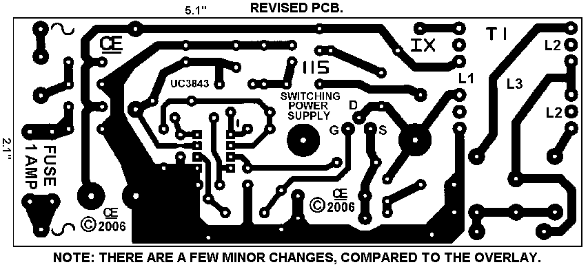
The Schematic
"I Assume No Liability from the Construction or Use of this circuit"
All Imformation in this Article is "Copyright protected".
Chemelec
*Copyright © 2006*