Use Extreme Caution when building and using this circuit.
It Produces Dangerous High Voltage Levels.
And the Capacitor "CX" Will still have a Substantial Charge, After the Battery power is Removed.
These Voltages at the Currents available May Kill You!
Supply Voltage is 12 Volts and Nominal current draw is dependent upon T1's construction
and Dead Time Settings you choose.
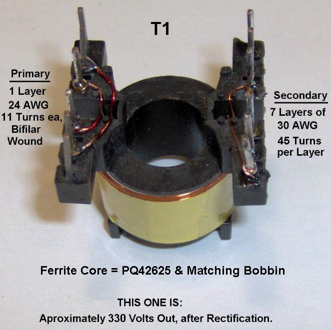
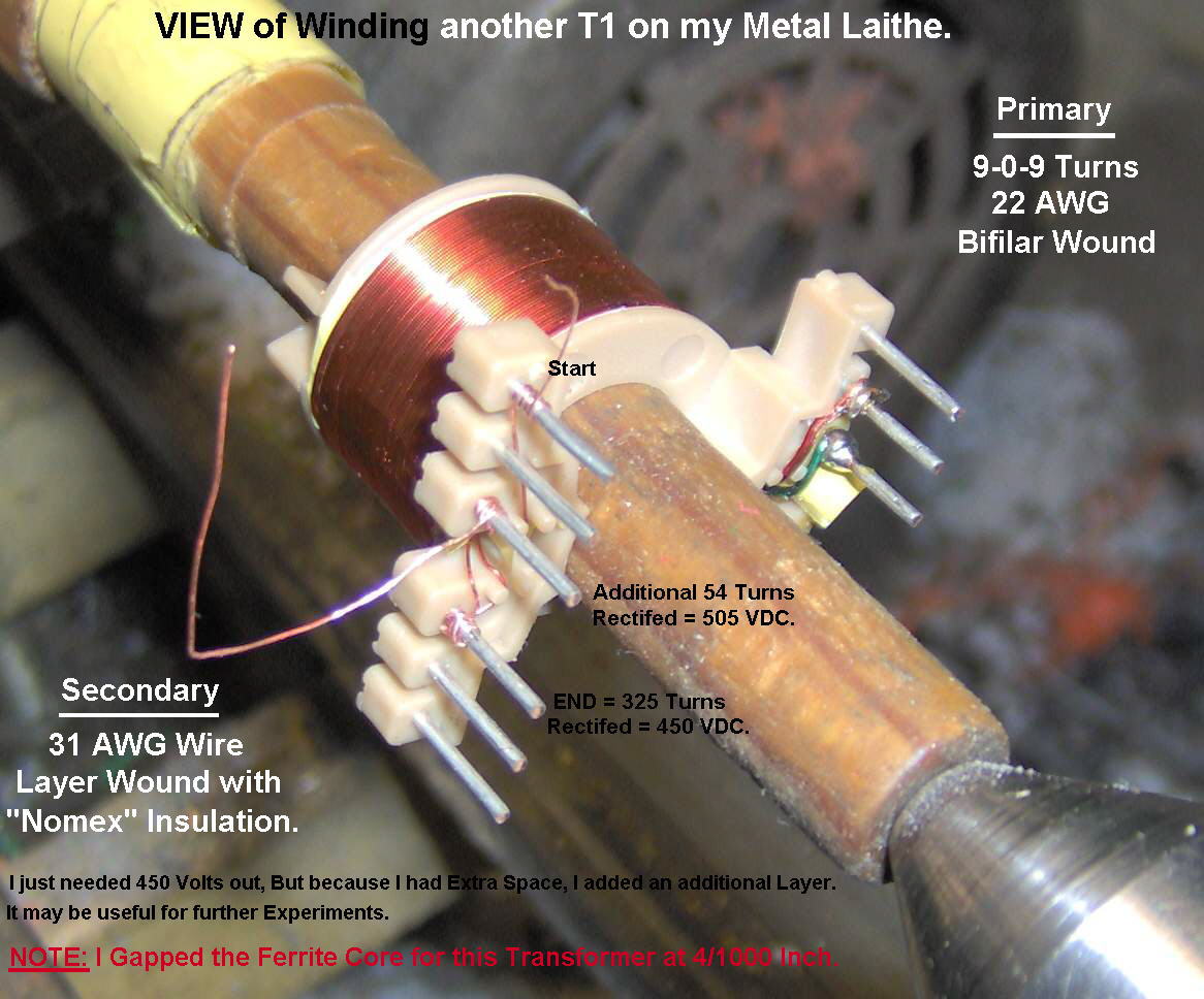
T1 is a Custom Made Ferrite Core Transformer, Which you must wind yourself.
A Larger transformer could be used, Larger Heatsink and Multiple Storage Capacitors
(CX on the Schematic) can be used in Parallel to increase the storage current.
Output Voltage depends on the number of Secondary Windings of T1.
It can be just around 300 volts as is used here, or even 1000 volts or more,
as needed by the strobe Tube you have.
However the Higher the Capacitance of CX, the shorter the tube life.
Especially if the Watt Seconds Exceed the Specifications of you tube.
The Output Current of the Transformer, Required to Charge "CX", is mainly determined
by the Wire Gauges, Core Size and Input Current. Also the Ability of the heatsinks to
keep the Mosfets cool. The heatsinks I show are only suitable for somewhat lower powers.
It is Impossible to create a Design that suits Everyones Needs.
I can possibly supply a Strobe Tube rated at 4 Watt-Seconds, that uses a typical voltage
of around 300 volts and has an estimated life expectancy of 1,000,000 flashes.
But there are MANY, Much Higher Strobe Tubes Available from various sources.
"The Deadtime Control" Determines Pulse Width which controls Drive Current.
"The Frequency Control" Determines Frequency of Oscillation.
Depending on how you wind T1, Increasing Frequency may help for faster charging.
"The Rate Control" Is adjustable over a reasonable range, But if its Too Fast
for you, Change the 68K resistor to a 220K or higher,to Slow it down.
Or Possibly use a 2M5 Pot for a Wider Range of adjustment.
Typical wattage ratings for these tubes are measured in "Joules" or "Watt Seconds".
And according to the "ARRL Handbook", a Joule is one watt-second,
and the formula they give to Calculate the appropriate Capacitor is:
However the Capacitor in a Strobe circuit doesn't discharge to Zero Volts.
Therefore, assuming a slow flash rate and achieving a charge voltage of 340 volt
340 - 110 = 230 volts drop.
230 times 230 = 52,900
52,900 times .00016 = 8.464
8.464/2 = 4.232 Watts Dissipation.
I am not 100% sure on my evaluation of this, but it sounds logical to me.
This circuit can provide a Very High Powered Strobe, for a variety of Portable Uses.
"I can supply these Cores and Bobbins for T1,
And many other Parts, For the Circuit as Shown here."
 Here is a Link to Cores and Bobbins I can Supply
Watt Seconds = ((Volt2) X (Capitance in Farads))/2.
The Minimun voltage I measure is around 110 volts.
with a capacitance of 160 Mfd, (.00016 Farads) I come up with a wattage of:
If anyone has other info, I'd be interested in seeing it.
CLICK HERE, To read a Letter about this, from a reader"
Final, Strobe-2 Schematic
Note: The "Snubber" Values Shown, Will Vary with Different Transformers.
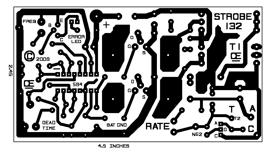
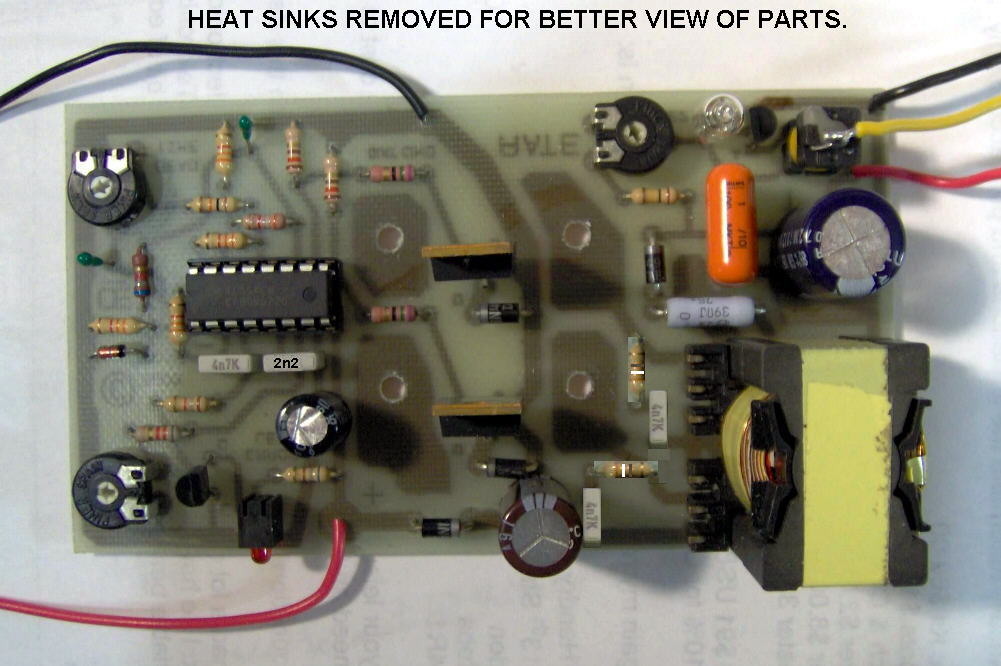
Final, Strobe-2 "Circuit Board"
WITH BETTER HEATSINKS.
Final, Strobe Overlay"
I plan to put Part Values on this, in the near future.
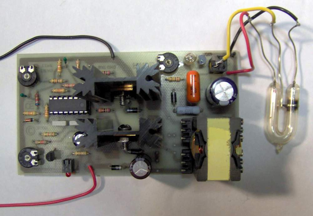
Proto Strobe, Connected to Small 4 Joules Strobe Light.
Sorry this is the only bulb I have at this time.
"First Test Transformer, used on this Prototype"
This Bobbin is a PC-B2625-LA, Made by "Magnetics"
The Core for this bobbin is a OPQ-42625. (Not Shown here)
"Another Transformer I Made, for 450 VDC"
Also this same Bobbin, PC-B2625-LA, Made by "Magnetics"
Again, the Same Core for this bobbin. (OPQ-42625)
Chemelec
*Copyright © 2009*