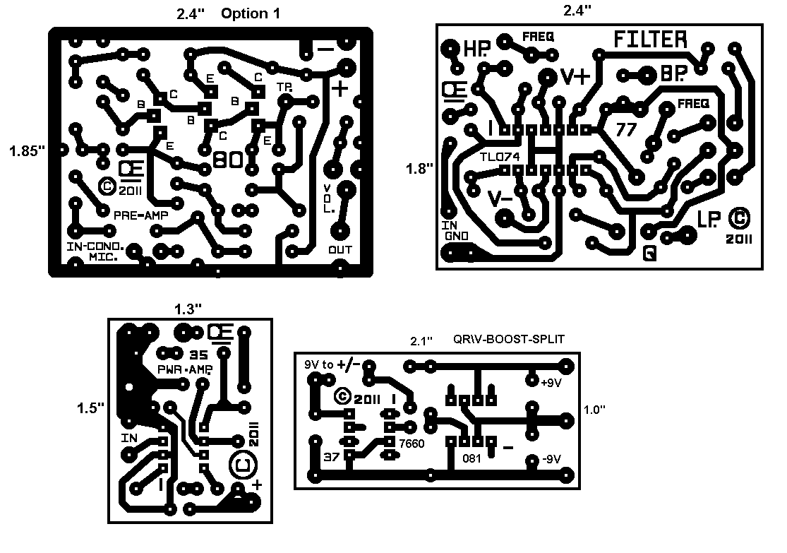
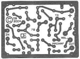
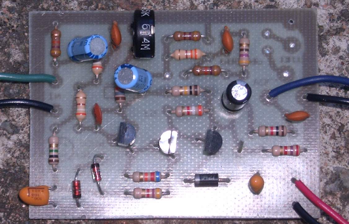
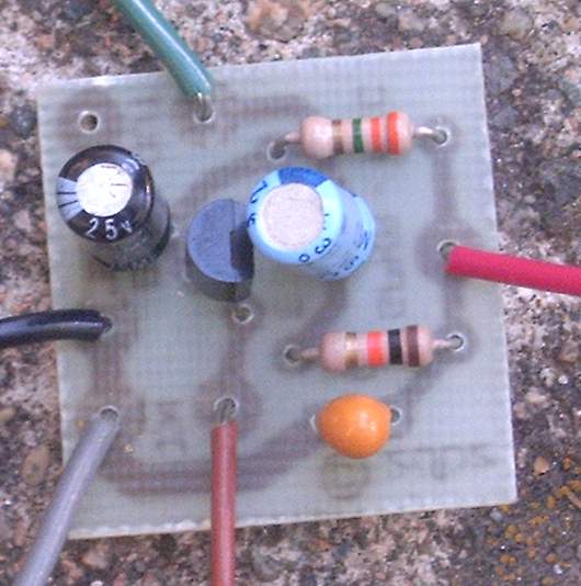
I prefer to use Individual Circuits for the Preamp, Power Amp, Filter, Etc. This makes it easy to change the boards, if you are not happy with any one of them.
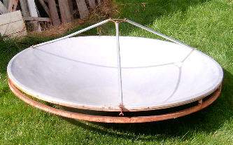
Weither you want a Parabolic Dish or a Shot Gun Type of Mic, the electronics is Basically the same. My Experience with Shotgun Mic's is not that good. I prefer the Parabolic.
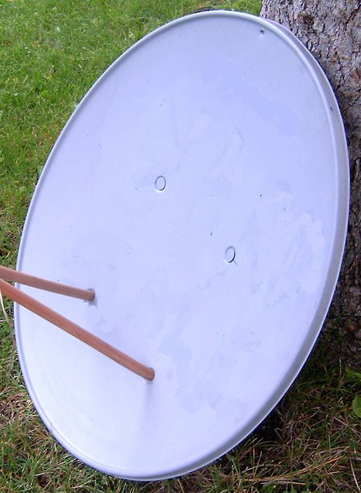
Parabolics should be at least 18 inches in diameter for this purpose. Smaller diameter Parabolics don't work very well in the Audio Range.
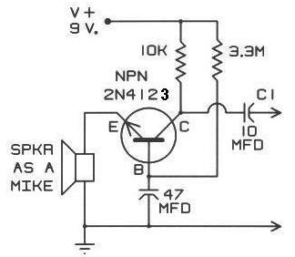
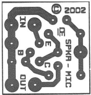
Any Type of Microphone can be used, But I prefer using a speaker as a Microphone. It has more surface area and typically a reasonable frequency response for this particular application.
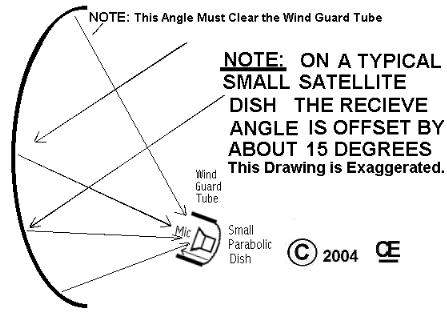
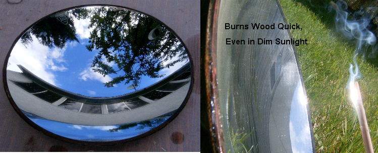
However an Electric (Condensor) Microphone will give a Better Frequency Response. But these Mic's are Small, so they have the Disadvantage of being able to catch all the Reflected signal. "This is Especially true" if the Parabolic dish is not a Really High Qualtity one, with a pin-point focal point.
For a better setup, Use a Large parabolic as your main dish and a Small 2 or 3 inch parabolic behind the Mic. This Smaller parabolic will catch any signals that are missed and reflects them back into the main dish.
Additionally, the Microphone should be Shielded from any Wind coming in from the sides.
"Go To My Home Page"
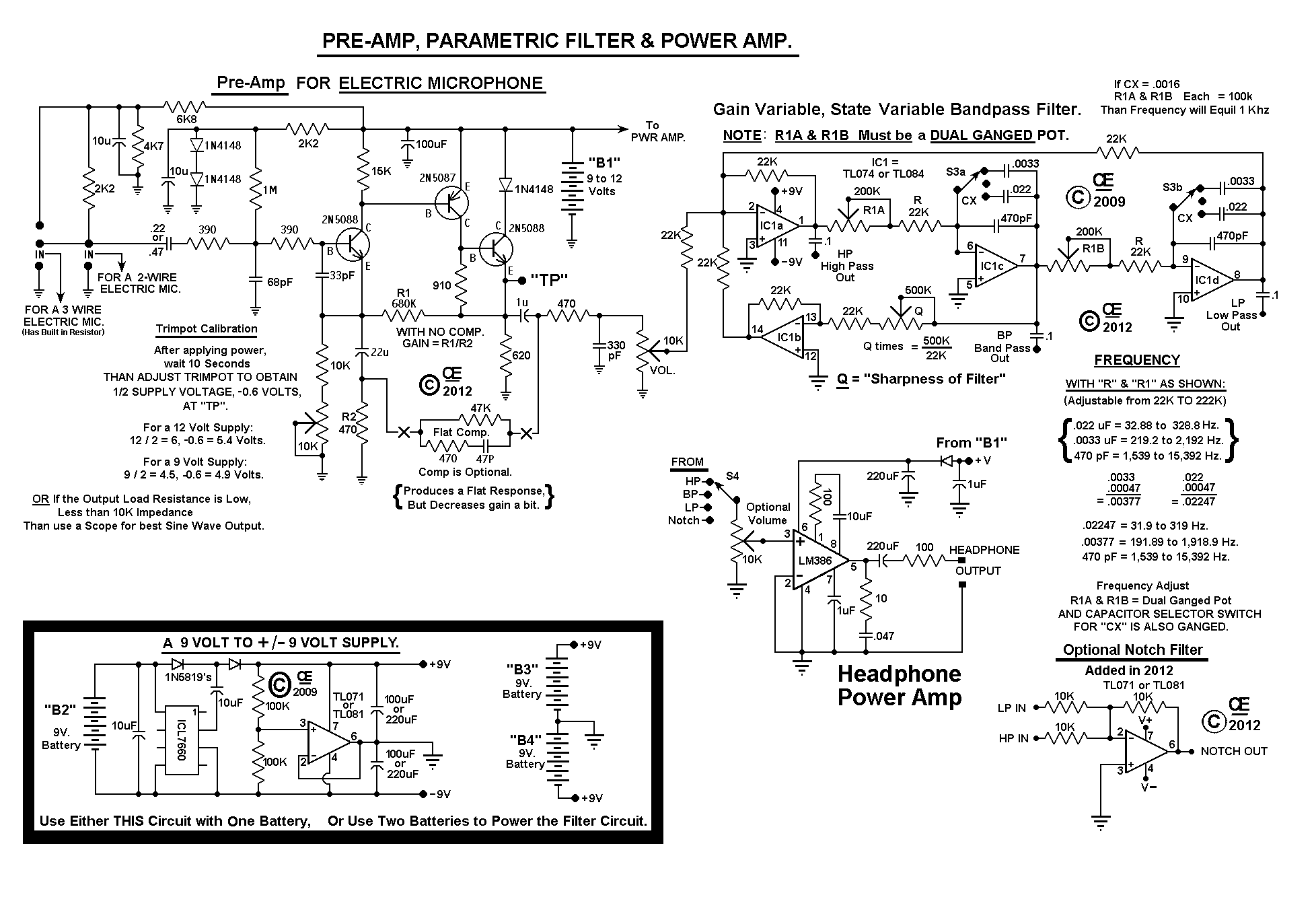
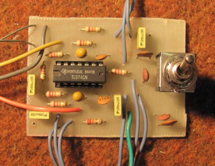
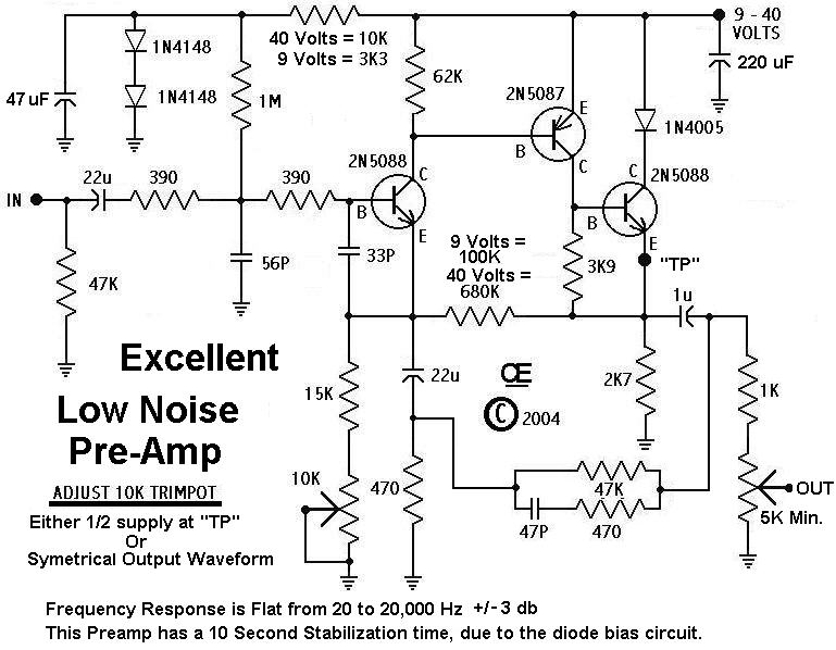
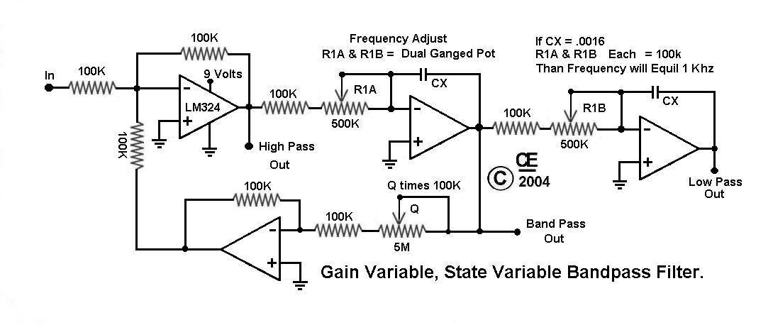
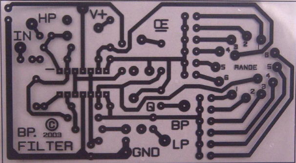
NEW REVISED Schematic With Filters. Posted Here on October 22, 2011. This Revised Preamp allows for use of Electric (Condensor) Mic's and a Range Switch for Either the BP Filter, A High Pass Out or a Low Pass Out. It also uses a 3 Position, Center Off, Toggle Switch, to give Three Frequency Ranges. (The Previous design used a Less Common Rotary Switch)
Optional "NOTCH FILTER", Added in Schematic on April 9, 2012. However this will require a 4 Position Switch
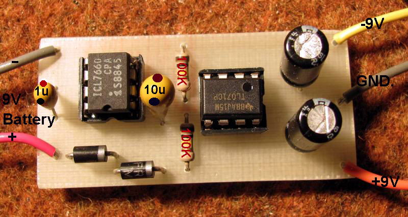
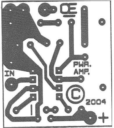
from 9 Volts, Overlay Picture.MORE NOTES:
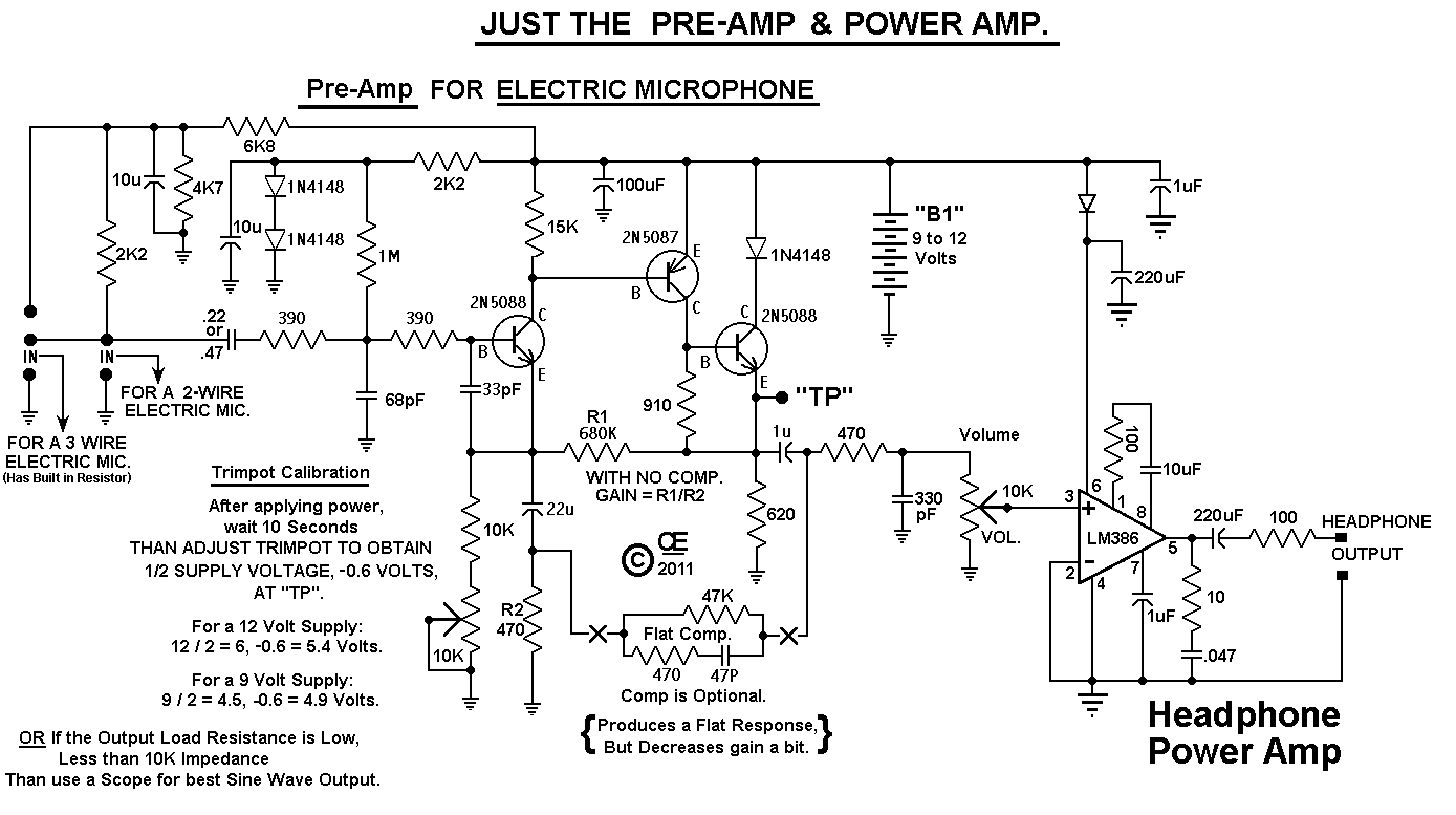
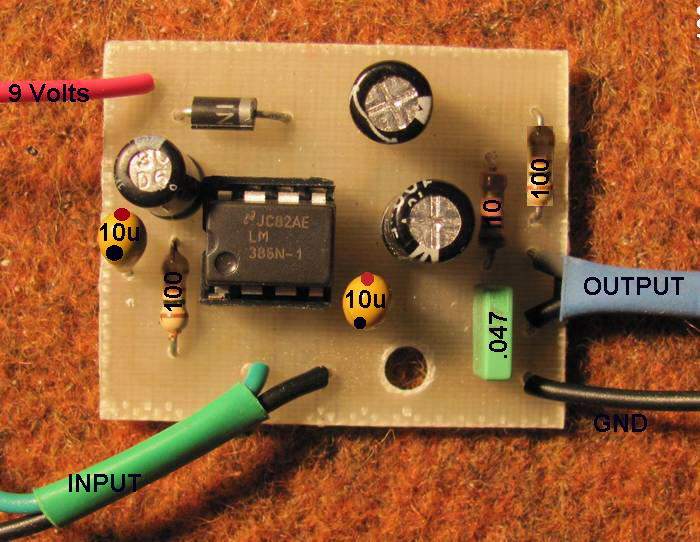
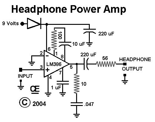
The Preamp & Power Amp just require a single 9 or 12 Volt Battery.
The Filter Requires a "Plus and Minus", 9 or 12 Volt Supply. This can be Either 2 Batteries connected in Series, with the Ground coming from the junction between these two batteries, Or by using the Preamp/Power Amp battery and the "9 to +/- Circuit" to power it.

All Imformation in this Article is "Copyright protected".
Chemelec
*Copyright © 2004 & 2011*