"A Pulse Width Modulation Control"
and Control High Currents to run lights or motors.
Article Created: "Mar, 2003"
Revised: "June 29, 2014"
The first circuit below was built for 12 volt DC operation, but can be operated at other voltages assuming you don't exceed the 555 operating supply voltage.
New Designs: at the bottom of this page, will allow for MUCH Higher Power for both N & P Mosfet Circuits.
On all these circuits, Changes to the Potentiometer value as well as the capacitor on pin 2 of the 555 can be made to change the operating frequency. A lower value capacitor will result in a higher frequency. However I don't suggest a much Lower value Potentiometer, Higher is OK!
The duty cycle range is determines by the value of the pot plus the two 1k current limiting resistors, one at each end of the pot.All of these circuits are relatively stable in Frequency as the Pulse width changes!
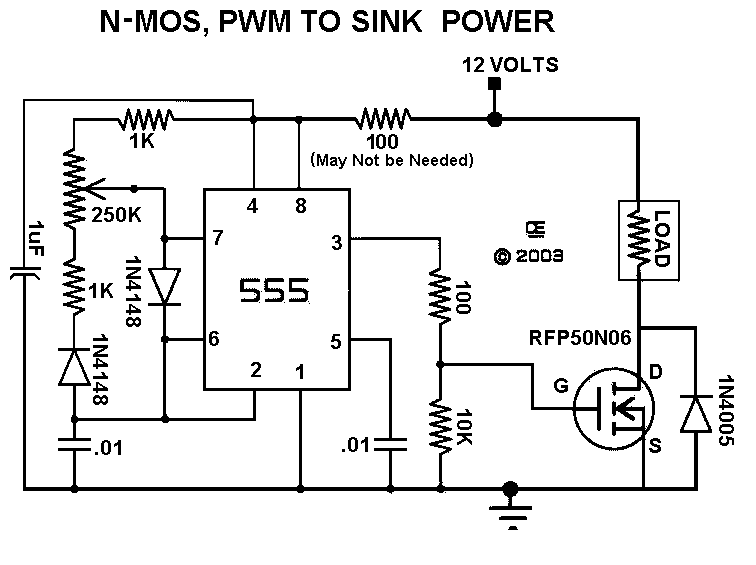
Origionally I used RFP50N06 N-Channel Mos-Fets, but now their are Better ones available.
I have provided for a heatsink on the circuit board of the First Circuit. It may or May Not be needed for your particular application. Definately not a problem when drawing only one or two amps. But at High currents, it would be advisable to mount the Mos-fet off board and connected to the board with reasonably short wires. (under 8 inches)
In the event of running high current motors, over 5 amps (?), there might be large spikes that can distroy the 555. Replacing the 1N4005 diodes with Schottkey diodes or 15 volt Movistors will definately help.
For Real High Currents, it is possible to Parallel two or more Fets. But there should be independent Gate resistors, as well as a 0.05 to 0.1 ohm Source Resistor on each Fet. This helps distribute the current evenly between all the Fets.
NOTE Versions-1 & 2 using N-Mosfets Will "Sink" the Power. For use with "NON-Grounded Loads".
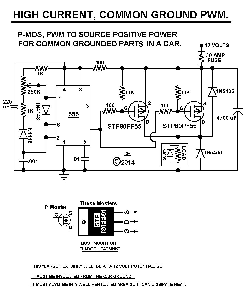
Version-3, Using P-Mosfets will "Source" the Power.
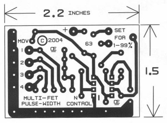
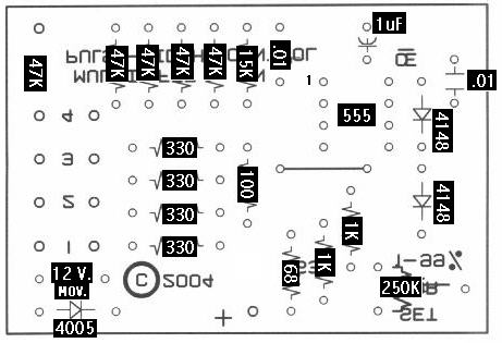
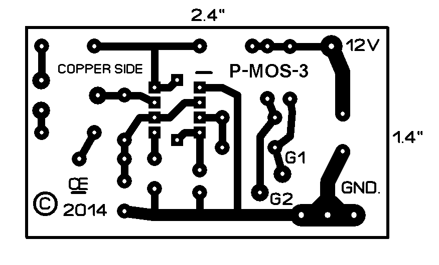
For use wih "Grounded Loads".Etched and drilled PCB's as well as Parts are usually available for these Circuits.
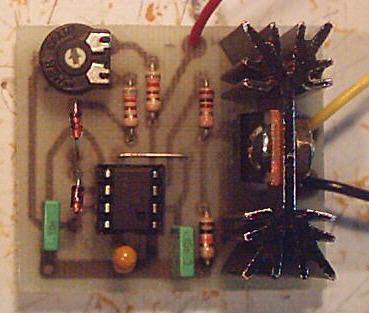
A Picture of the FIRST "Proto-Type" I made and tested
Note this proto does not have the 1N4005 diodes.
Also the Trimpot can be a regular pot, wired off-board.
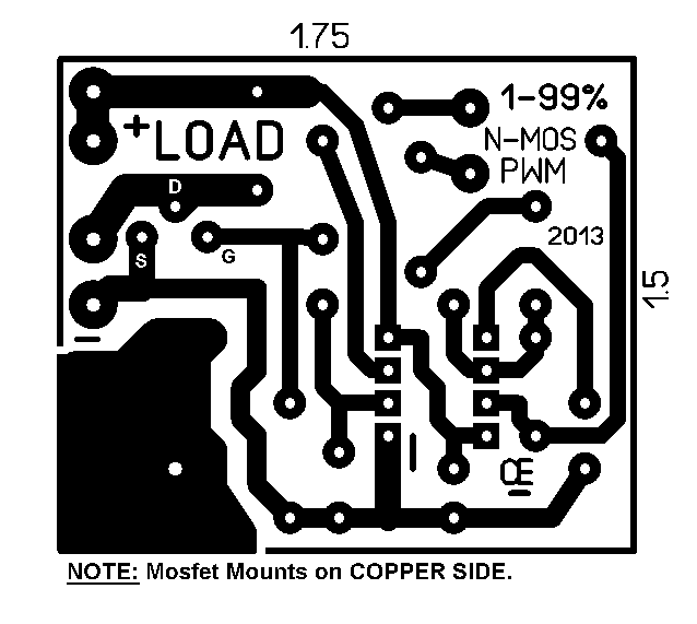
My Revised PCB has a DIFFERENT LAYOUT for the Mosfet.
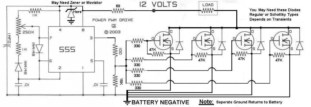
"The Schematic for Version-1 with an N-Mosfet"
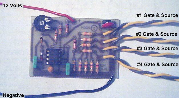
Version-2, A HIGHER POWER, Up to "4 Paralleled" N-Mosfets. With the 250K Pot and the .01 Cap on Pins 2 and 6 it will run at about 500 Hz. Changing this cap to a .0047 it will run at about 1.15 Khz. Changing this cap to a .001 will make it operate at about 4.8 Khz. Changing the Pot to a 100K and using a .001 will give a frequency of about 11Khz.
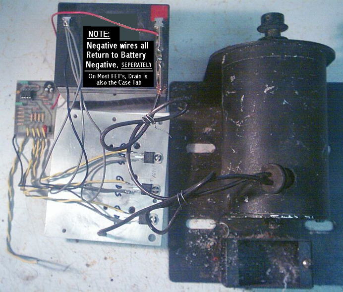
This Circuit as Pictured was able to push Over 30 Amps into this motor, but even with a battery charger, it was Sucking that Battery down. This motor is The Biggest Load I have available for testing this circuit and I only used "three" Mos-Fets on this test.
My Version-3, A HIGH POWER, P-Mosfet Version. It can be used with either One or Two Mosfets.
All Imformation in this Article is "Copyright protected".
Chemelec
*Copyright © 2003 and 2014*
