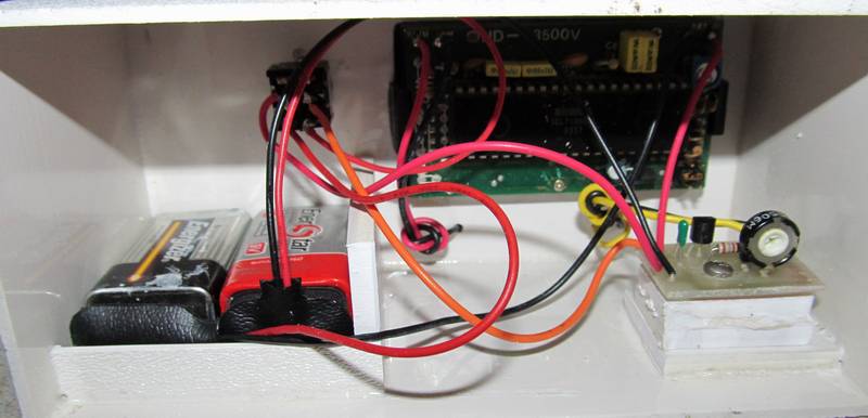
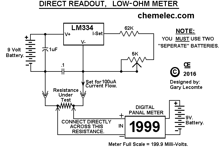
In All these Circuits, You MUST use Two Seperate 9 Volt Batteries. One for the Digital Panal Meter and one to supply power to the LM317LZ Circuit. "These Batteries will Last for Years, unless you do a LOT of testing", And a Single "DPDT Switch" can be used to turn "On & Off" Both these Batteries at the same time.
I Recommend the LM317LZ, which is the 100 mA, T0-92 version of the Normal LM317. But you can also use the LM317, in the T0-220 Package, if you want. It is Just BIG in Size.
Calibration with an Accurate Known Resistance:
If you have an ACCURATE Known Resistance, than you can just Calibrate with that Resistor.
An ACCURATE Resistor between 1.500 and 1.950 Ohms is Best for the Low Range. (1.999 Ohms.) Or an ACCURATE Resistor Between 15.00 to 19.50 Ohm is Best for the Higher Range. (19.99 Ohms.)
I can probably Supply one that is Quite Accurate!
Alternately, Calibration by Setting Current Source:
For the 1.999 Ohm Tester, the Trimpot MUST be Set PRECISELY to deliver
100.0 mA out, to get Truly Accurate Resistance Measurements.
(Alternately, a 4 1/2 Digit meter would read Down to 1.9999 Ohms.)
When reading the Resistance at 3rd or 4th Decimal Place you can get Variations,
caused by slight changes in Temperature, thus causing slight changes in the resistance reading.
For the 19.99 Ohm Tester, the Trimpot MUST be Set PRECISELY to deliver
10.0 mA out, to get Truly Accurate Resistance Measurements.
(Alternately, a 4 1/2 Digit meter would read Down to 19.999 Ohms.)
Ideally you need a VERY ACCURATE Milli-Amp Meter to adjust this Correctly. (And like Any Test Equipment, This Calibration should be Re-Checked once a year or so.) ** My Calibration Meter is a 4 1/2 Digit DMM, "So 100.00 mA setting Capability".
The Meter Leads MUST Connectly DIRECTLY Across the Resistor or Wire to be Tested. DO NOT CONNECT IT to the Clip On Leads, that connect to the Resistance under test, As this will give FAULTY Readings, as a Result of Contact Resistance.
The Display will read out Directly in Ohms, Between 0.001 up to 1.999 Ohms, Or Between 0.01 up to 19.99 Ohms.
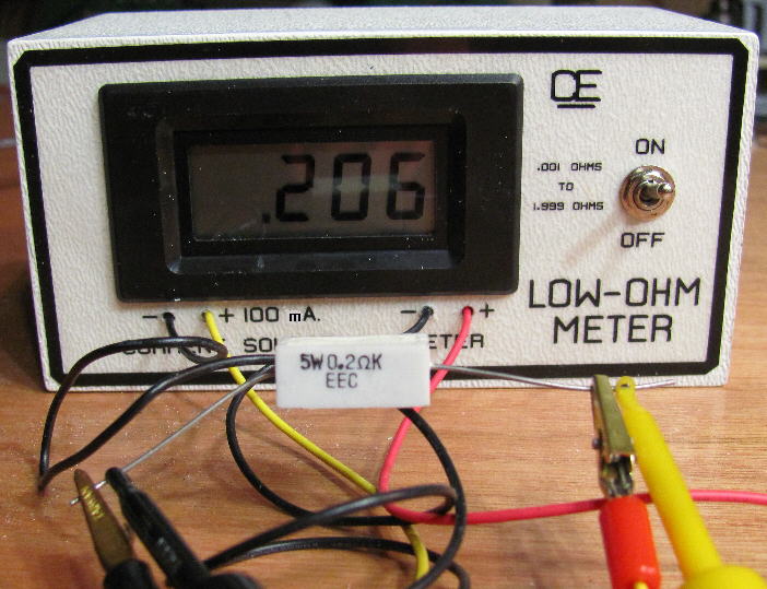
AS A OUALITY TEST for my 1.999 Ohm Meter: I connected my 100 mA current across a Single Conductor of 22 AWG Bare Copper wire that was about 16 inches long, "but exactially 12 inches long between my Meter Test Leads". And it measured 0.016 Ohms.
Looking at my Copper wire Chart, it tells me: 22 AWG has 16.46 Ohms per 1000 feet. So that is 0.01646 Ohms per Foot. So I AM VERY HAPPY with this result! (BUT Not All Copper Wire will measure the same, Due to possible Impurities)
Alternately You could Calibrate this meter using this 1 Foot of 22 AWG Copper Wire. Cut the Wire a little over 12 inches in Length. (actual Length is not important.) Than connect the Current Source Leads with one at each end, And Clip the Measurement leads so they are Precisely 12 Inches apart on this wire. Lastly, Calibrate the meter to read 0.0165 Ohms.
OR You could just use 1 Foot of 32 AWG wire to Calibrate this Ohm Meter. Cut the Wire a little over 12 inches in Length. (actual Length is not important.) Than connect the Current Source Leads with one at each end, And Clip the Measurement leads so they are Precisely 12 Inches apart on this wire. Lastly, Calibrate the meter to read 0.167 Ohms.
For the 19.99 Ohm Meter, You could just use a 1% Precision Resistor In the 15 to 18 Ohm Range, to Calibrate this Ohm Meter. This is Not the Best, But it Still should be Quite Accurate.
I could also create a Milli/Micro-Ohm Resistance Meter, But the real Problem would be the Accurate Calibration of the current source. Especially since current Sources can Vary Somewhat as Ambient Temperatures Change.
On June 24, 2014 I REVISED the Schematics and PCB's for
These changes make the Calibration Somewhat Easier.
Both of these units.
The PCB's and All parts are available from me.
Or I can provide a Complete Low Ohm meter, Assembled and Calibrated in a "Custom made Case".
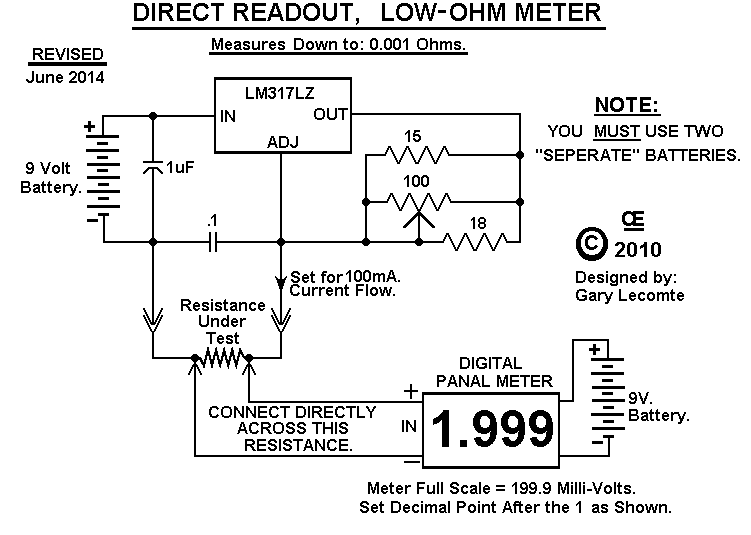
 .001 to 1.999, NEW Low Ohm Meter Schematic.
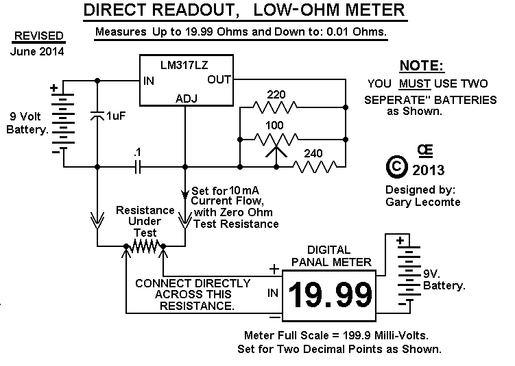
.01 to 19.99, NEW Low Ohm Meter Schematic.
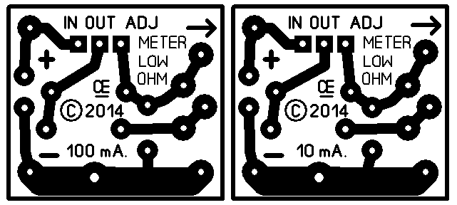
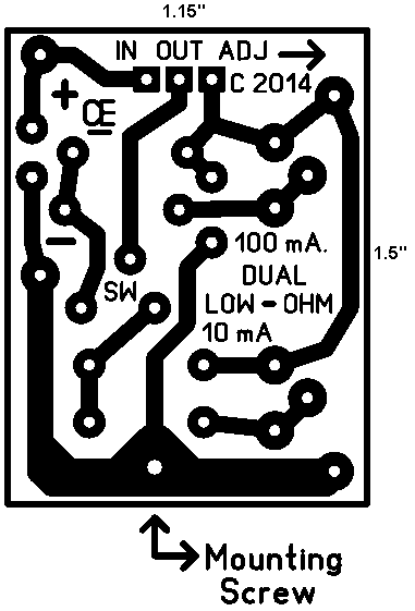
PCB for the 10mA or 100mA Current Source.
This is a Small Circuit and can be built without a PCB,
But this PCB is Available, If Wanted.
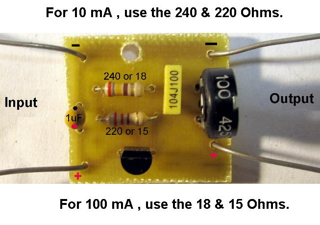
PCB Overlay for the 10mA or 100mA Current Source.
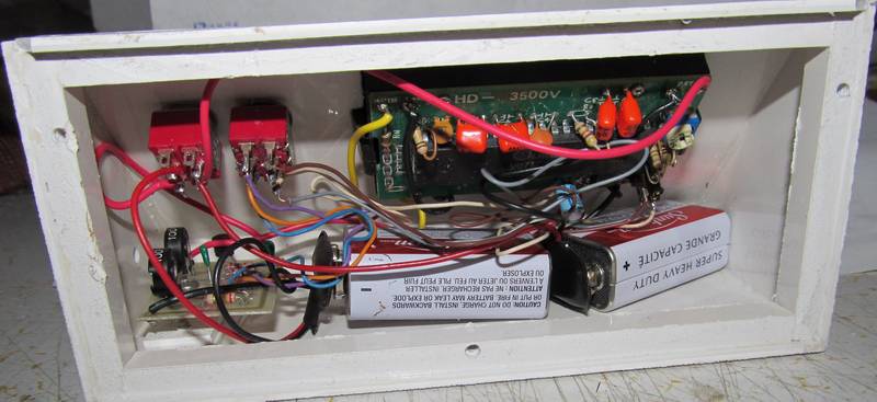
My Completed 1.999 Ohm Unit.
You Could use a DMM instead of this Panal Meter, But you will Probably Lose One Decimal point of Sensitivity.
The Front Decal was created in a small Cad Program and Reverse Printed on "Transparency Film".
Than Sprayed with "3M's Spray Mount Adhesive", let dry and than applied to the front.
Because it is Reverse Printed, the writing Can't rub off.
View of a 19.99 Ohm unit I built for a Customer.
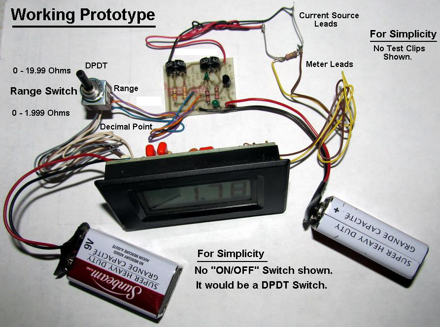
 A Dual Range, Low Ohm Meter Schematic.
Assembled PCB of Dual Range, Low Ohm Meter.
The PCB for this Dual Range, Low Ohm Meter.
My Initial Test Setup, for this Dual Range, Low Ohm Meter.
Note: This Also Corrects the Decimal Point on the LCD Display.
The Decimal Connections on My LCD Meter.
A 0-1999 Ohm Meter Schematic.
I Designed this because of a Request from a person in the UK, But I have NOT tested it yet.
All Imformation in this Article is "Copyright protected".
Chemelec *Copyright © 2010 & 2016*
*Copyright © 2010 & 2016*