 9 to 15 Volt Operation. Can be used in a Motor Vehicle.
C-Mos Design, Low Standby Power.
4 Digit Enter Combination.
Unlimited Reset Keys, stops accidental entry by unwanted persons playing with
it.
Can be used with "Touch Pads", "Push Buttons" or a Phone type "KeyPad".
NOTE: High Sensitivity is NOT Required if using a "Keypad or Switches".
So the 1M resistors can be Reduced to 100K values if so desired.
For Really High Sensitivity, the 1M Resistors can be increased to 8.2M or even 10M.
Optional "Auto Reset" after X number of seconds.
(Eg: This causes the Lock to turn off "??" seconds "After the last number is
entered")
NOTE: If you do not want this feature, leave off "R12", "D3" and "C2".
And Changing R12 or C2 to higher values will increase this reset time.
(On my Truck, I punch in the Combination and Immediately open the door before
the solenoid resets. It works great and no chance of leaving my truck unlocked.)
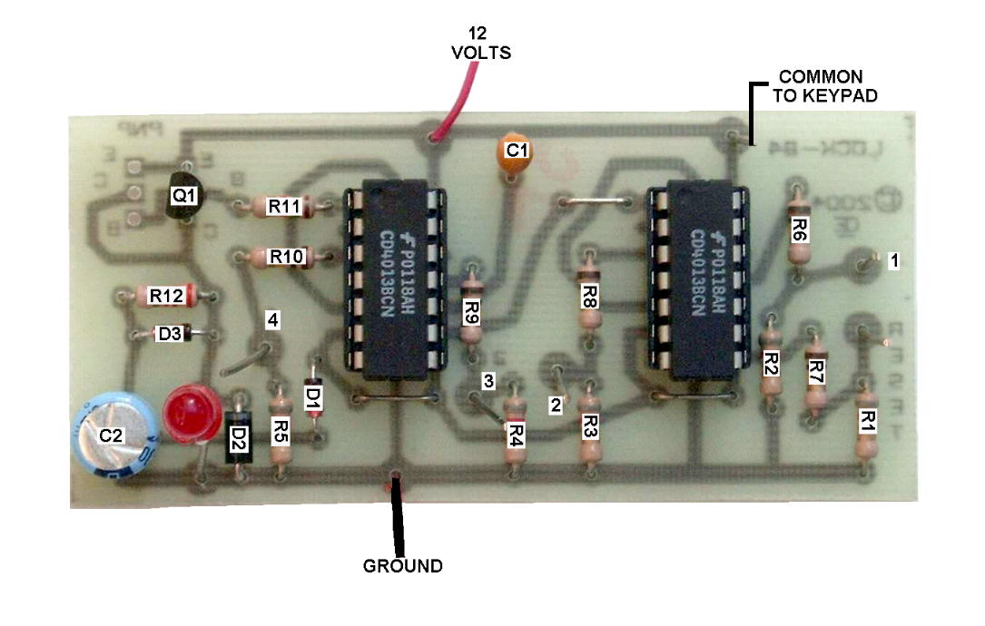
Further Info: The Circuit Board is Designed to accept 2 types of Drive transistors. I Used a 2N3906 in this schematic, but for Higher Current Drive for a Solenoid, You can use Various T0-220 PNP types of transistors. USE ONLY ONE OR THE OTHER, NOT BOTH. In the Picture, I just put a Resistor and LED, where the Solenoid should go.
Although Key Pads are Expensive, they do look nice. The Keypad I used was a Part Number 88AC2-162, Made by "Grayhill", But now its DISCONTINUED. Alternately Grayhill make others. Such a a 88AC2-172. Or go to www.grayhill.com to see what else is available.
Because this is a C-Mos design and Highly sensitive, it is "MOST IMPORTANT" to Remove All Traces of Solder FLUX from the board.
NOTE for a Touch Pad: Touch Pads can be easily made with 1/2 inch metal pads placed about 1/8 inch apart. This could be etched in Circuit board, but a material that doesn't oxidize would be better. Also they MUST be Protected from Water or it will Continuously "RESET", Stopping you from opening it.
Note: The Lock System on my truck is a Slightly different design than this circuit, but I use the Same Keypads on my truck and find they last about 10 years before needing replacing.
Inside my truck, I have a "Momentary Pushbutton" that supplies power directly to the solenoid. This is used to activate the solenoid and Exit the truck.
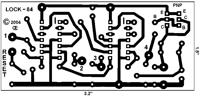
PARTS LIST
R1, R2, R3, R4, R5 = 1M or 100K R6, R7, R8, R9, R10 = 100K R11 = 1.5K OHM R12 = 220 OHM Q1 = 2N3906 C1 = 1 uF TANTALUM C2 = 100 uF ELECTROLYTIC IC1, IC2 = CD4013BCN D1, D3 = 1N4148 D2 = 1N4005 A Common Anode Keypad or Switches of some kind.