
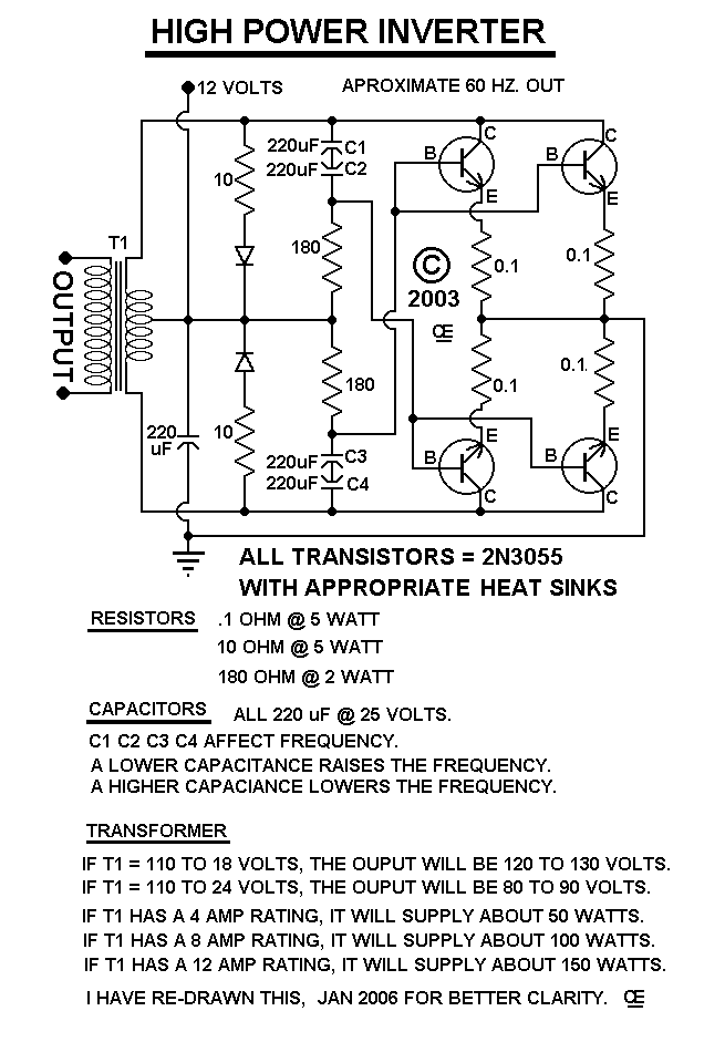
This circuit will provide a fairly stable "Square Wave" Output Voltage.
Frequency of operation is Mainly determined by the 220 uF Feedback Caps.
Currently about 60 Hz.
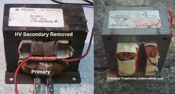
Various "off the shelf" transformers can be used.
Additional Transistors can be further paralleled for higher power.
This is not by any means, the most efficient design, but it is "Simple and Works".
It is recommended to always have a Load connected, when power is applied.
Or Custom wind your own.
Or for low power, remove two.
Additionally Other transistor types can be used.
All Imformation in this Article is "Copyright protected".

 Chemelec  *Copyright © 2004*