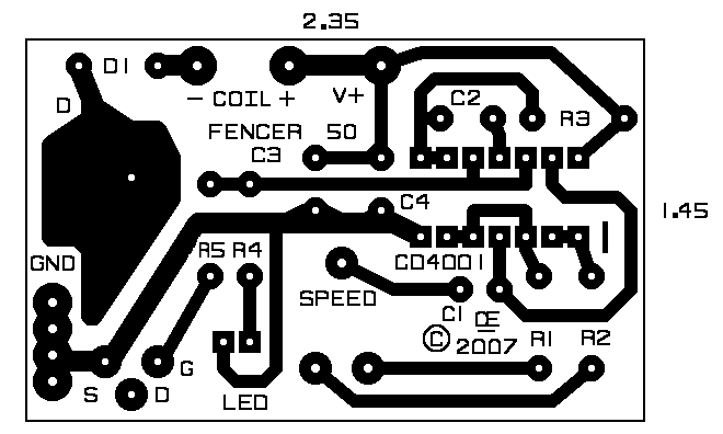
"Cmos, Electric Fence Design"
"FENCER-1"Created: "Aug 13, 2007" Updated: "April 26, 2018"
IMPORTANT NOTE: Car Coil Fencers are NOT Suitable for LONG Fences. A Fence having a Single wire and Shorter than 1 KM is probably OK.
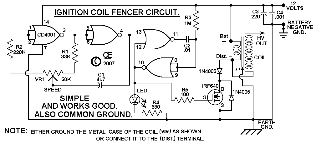
This circuit design is based on a C-Mos chip to Drive a Car Ignition Coil.
This is a Very Simple and Efficient Design for an Electric Fence. It puts out a Very high Voltage Current pulse, yet it draws a very low "AVERAGE CURRENT DRAW" from the battery or Power supply.
Note: Just Using a Battery Charger is NOT a Suitable Power Source
As Accurate as I can Measure, the "AVERAGE Current Draw" varies between:
20 uA at at Slow Pulse setting to about 85 uA at the fast pulse setting.
So Battery life is "Really Good" and this makes a Good Electric Fence.
NOTES:
Due to a High Peak Current Draw, this Fencer will NOT work properly,
just running from a Power Adapter or a work-bench power supply.
This Electric Fence Should be powered by a 12 Volt Battery and this battery
Should have a Trickle Charger on it.
A Small "Solar Panal" would do this quite well.
(Occassional Cycle Charging a car battery or Sealed lead acid Battery is not a good idea.)
THE CASE OF THE COIL SHOULD BE CONNECTED TO EITHER GROUND OR THE DIST. TERMINAL.
FAILURE TO DO SO, MAY RESULT IN THE CASE BECOMING ELECTRICALLY HOT.
On Some Ignition Coils, the Points Terminal is Marked as "Dist" for Distributor
and on some others it is marked as "Neg" or "-"
C2 Determines the duration of the pulse and
VR1 determines the number of pulses per second.
The Values shown give good Results.
The LED and R4 are Optional. They just show its working.
The HV Output Spark should be about "1/2 Inch inch length".
However, When operating this from a Power Supply, It may Not produce a Good Spark.
This is due to a High Internal Resistance in the Supply.
Adding a 1000uF capacitor across the +/- of the PCB should correct this.
This Cap my also be required if you use a Battery but with Long Power Leads to the circuit board.
After assembly of the Circuit board, All Solder Flux Should be Removed from it.
Solder Flux CAN Become Conductive in the presence of Moisture and this can
result in eventual failure.
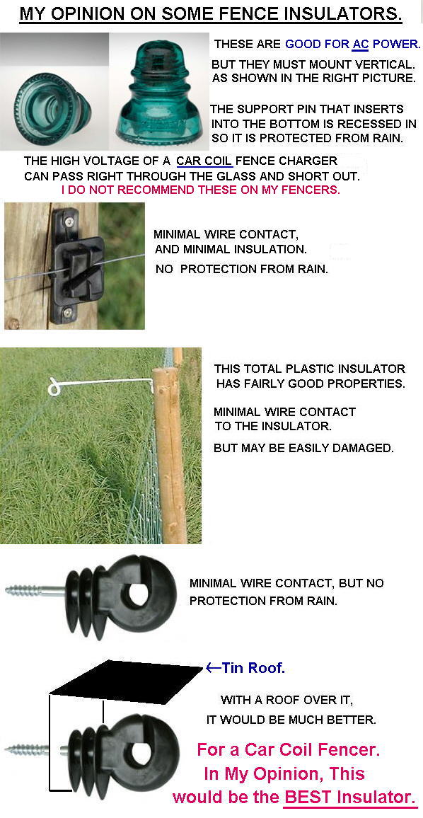
Also both the "Circuit Board and Coil Must be Protected from Rain and Snow".
Suitable Insulators must be used on the fence, or Rain will short it out.
It Won't damage the circuit if that happens, But it also won't shock anything.
A Kit of parts/pcb is available from me. (Excludes the 12 volt Car Coil).
Also Not Included in the kit, But I Recommend adding a 1 Amp
Inline Fuse between the battery and this circuit.
It MUST be connected to a Suitable Battery for it to work properly.
Most Battery Chargers are NOT good DC POWER as they Contain a Lot of AC Ripple.
 Click HERE:
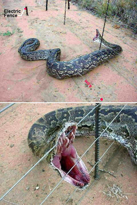
See what this Electric Fence caught in Arkansas.
It is 10 feet long and got stuck under the fence.
It Died there.
Obviously it was someones PET, that got away.
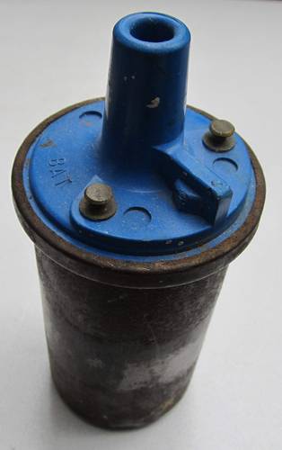 This is the Type of Car Coil that is Required.

All Imformation in this Article is "Copyright protected".
Chemelec
*Copyright © 2007 & 2014*