This circuit uses one tuned coil for on the door and just a single wire loop on the animals collar.
When the two coils come close together, it produces a signal that can cause a an LED to light and also trips a solenoid to unlock the door so it can open. Since all these doors are somewhat different, I leave The Solenoid and Mechanical Parts of this design for you to figure out.
The Main Advantage of this unit is it does Not Require any Battery on the animal, as is the case with most store bought devices for this purpose.
The Single turn coil can be joined with plugs so it can be removed easly. But if the plug comes apart or has a poor connection, the door won't open. So Better yet, make it Just Barely big enough to slip over the animals head, and Solder it to make a solid loop, than tape it to the animals collar. And the Larger the diameter of this coil, the Greater the Sensivity will be.
Also Important, the Cat or Dog door and the surroundings "Can't contain any large pieces of metal". (This circuit is also a Metal Detector and This detector see's the Single Loop of wire as a solid piece of metal.)
Additionally, the coil on the door needs to be mounted in such a way that the coil on the animal can actually get almost inside the coil on the door. Possibly a Round or Rectangular Extension, outward from the door will be needed to accomplish this.
Either way, the coil on the door will probably need to be mounted a few
inches from the door.
Ideally the coil on the door will have an inductance of about 150 uH.
My Inductance calculator can determine this for a Round Coil.
Just Click Here.
Enter the inductance as .15 Mhy (This is the same as 150 uH.)
Enter your Wire Size. (Probably either 26 or 28 AWG is best.)
Enter the Diameter of the coil in inches.
With the wires sizes above and this coil being taped together,
Probably just Enter .05 for the length.
Than click calculate, to get the info needed to make it.
Example: (.15 mH, 26 AWG, 7 inch dia., and .05 length)
Will Equil: 21 turns and require about 39 feet of wire.
Note: If you Bend this coil "Out of round", it will change the inductance,
But hopefully it will still be within the inductance range as is needed.
 "The Schematic for this detector"
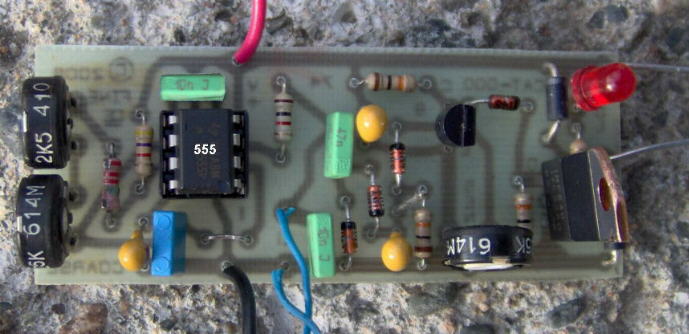
This is My Assembled "Proto-type Circuit Board"
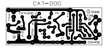
"The Circuit Board"
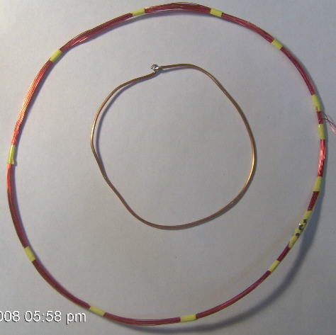
"Examples of the Coils"
This Smaller Coil is about 3.5" in dia., and the large one is about 7" dia.
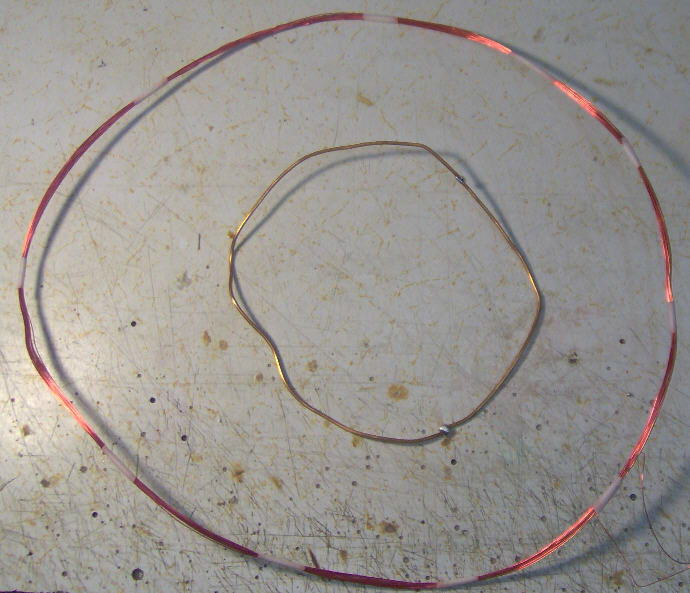
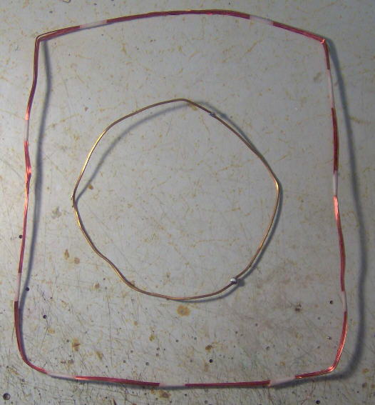
"Another examples of the Coils"
This Smaller Coil is about 5" in dia., and the large one is about 10.5" dia.
"Another examples of the Coils"
The larger coil above, bent into a 8" by 10" rectangle. When trimpots are re-adjusted, it also works.
Chemelec
*Copyright © 2008*
+++++++++++++++++++++++++++++++++++